

Well construction Well construction techniques
As described in the previous articles, the predominate number of wells have been formed by drilling. Well drilling can go from a few meters to a depth of more than 1000 m. Always dependent on the situation of the groundwater catchment. Ordinary diameters of the drill holes are between 400 and 1000mm. In certain geological and / or hydrological conditions, however, boreholes with a larger diameter are also carried out. In order to achieve a perpendicular and dimensionally stable borehole with reasonable effort, different drilling methods are used depending on the circumstances.
Drilling methods
It will distinguish between dry drilling and flush drilling.
Dry drilling
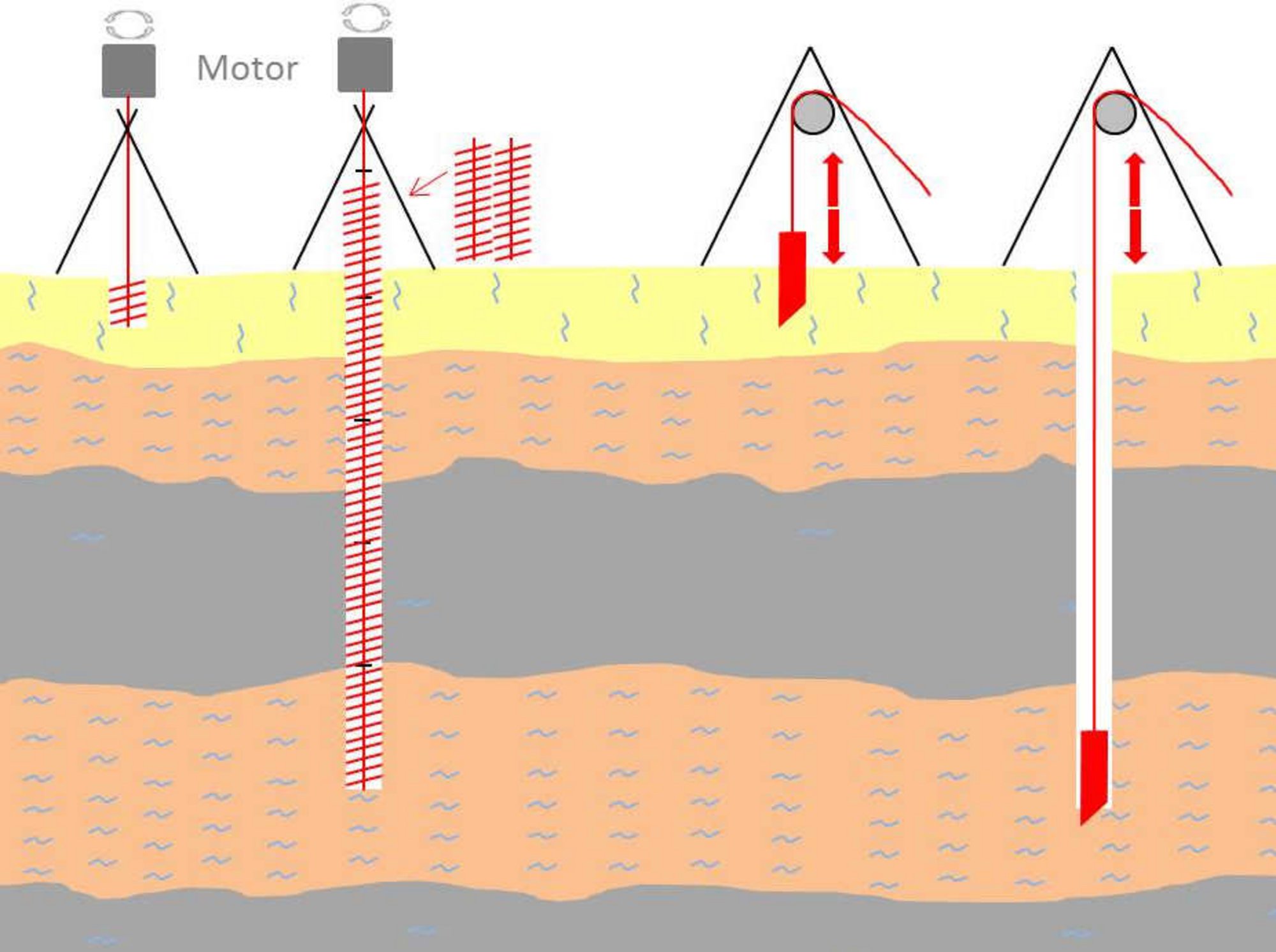
In case of a dry drilling, the drill pipe is continuously cased during the drilling process. This prevents the bore from being broken. The drill cuttings are conveyed by drilling tools and discharged upwards. If the substrate does not allow a simple bore, e.g. bedrock - the ground is first pulverized by an air hammer and then conveyed.
One method is that a drill head (e.g., a snail) is rotated and lowered by means of a linkage. As drilling progresses, more and more pipes are gradually being added. The drill cuttings are conveyed upwards by the spirals and removed.
Alternatively is percussion drill. The lifting and dropping of a heavy (50 kg+) cutting tool (e.g. a driving rod or mud auger) will chip and excavate material from a hole. The tool can be fixed to rigid drill-rods, or to al rope or cable. With a mechanical winch, dephs of hundreds of meters can be reached.
Rotary mud flush drilling
In case of a flush drilling, the drill hole is secured by the use of a special flush. Normally no piping takes place. The drill cuttings are loosened by the drilling tool at the well bottom and are conveyed upwards by means of a liquid, the drilling mud. First, the upper borehole mouth is protected with a standpipe. Immediately next to the bore a reservoir for the flushing is created. This is done either by a flat roll (flushing ponds or purging pits) or by special containers placed next to the drill hole. In the latter case, the standpipe is extended to above ground so that the containers can be connected. The flushing fluid is added and filled before the start of the drilling.
The flushing is executed as a direct or indirect flushing. In case of the direct flushing, also known as the rotary method, the flushing is conveyed by means of a pump in the drill string to the borehole bottom. By the drilling tool, normally a drill bit the resulting rock is loosened and released and transported upwards through the flushing circuit.
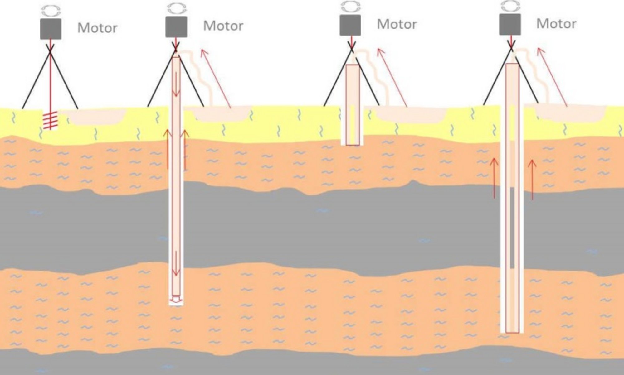
In case of the indirect flushing (‘reversecirculationairinjectiondrillingmethod’ or ‘inverseddrillingfluidcirculation’), the drilling mud enters the annulus between the drill pipe and the borehole wall in the borehole. By blowing air into the boom or by connecting a suction pump, the rinsing liquid rises upwards in the drill rod and thus brings out the drill cuttings.
The drilling mud consists mostly of water. In order to be able to support the drill hole sufficient and the drill cuttings can be discharged quickly enough flushing additives are added to the water. Bentonites, polymers and other additives are used for this purpose.
In case of very hard formations such as rock, the bore can be drilled as a so-called “borehole drilling”. Thereby the drill chisel is vibrated as in case of a percussion drill to increase the release energy. The drive is effected by the drilling rinse, which can even be used in the form of air in this case.
The drilling tools (wing chisel, roller chisel, flat head chisel, etc.) used in the flushing borehole are more or less heavily stressed depending on the geology. Usually the drilling tools are panzered with a special wear layer, which can be renewed again and again. Tungsten or diamond sheeting can also be used.
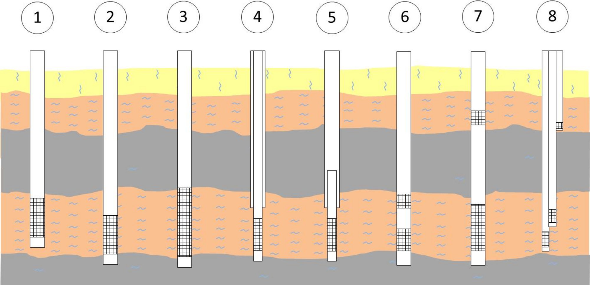
Different types of construction
- Incomplete expansion
- Complete expansio
- Rigid expansion
- Lock tube expansion
- Lost expansion
- Filter with blind tube section
- Step filter (not permitted)
- Multiple filter
Which type of expansion or construction is selected by the well builder depends on the local conditions and the requirements that the new well has to deal with. Each of the remarks has its advantages and disadvantages.
Requirements for filter gravel
Filter gravel AQUAGRAN® must be very hard with a SiO2 content of more than 96% and must be precisely classified. In Germany the details are regulated in DIN 4924. With regard to the chemical composition, the filter gravel must be provided such no water-endangering substances are released and the gravel is inert.
The filter gravel has various secondary tasks in the well. On one hand, the filter tube is supported and held approximately in the middle of the bore. On the other hand, due to the edge-rounded shape, which results in a form-fit in the filling, the forces occurring due to the weight are mainly removed from the borehole walls.
Remark
For a better understanding, you can imagine a multi-inch pipe, which is hanging on a house wall which is 20 m high. If this tube is filled with filter gravel, everybody can hold it with one hand despite the great weight which is produced in the vertical. The reason for this is that the individual grains are "jammed" (or, technically speaking, transfer the force (by own weight) to the pipe). The whole weight does not weigh on the hand (or in practice on the filter cage).
The main task of the filter gravel AQUAGRAN® is to keep the access to the filter cage open. The water in the aquifer should flow into the pipeline as unimpeded as possible. The German (norm) standard prescribes that the filter gravel may have only a small amount of lower grain (smaller than the lower nominal grain size). The proportion of the lower grain is particularly harmful, since the small grains can clog the filter cage. The proportion of over corn (bigger than the upper nominal grain size) is also regulated, the disturbances due to over corn being not so serious.
Since the filter gravel is very hard with its high SiO2 content, they are often brittle also. There is a risk due to improper handling, more sub-grain is produced than in the delivery condition. In any case, avoid improper handling (see ‘Recommendations for handling of filter sand and gravel’). DIN 4924 defines various filter gravel sizes (see AQUAGRAN® sizes DIN 4924.)
The gravel is brought in by pouring or rinsing. The pouring rate is to be considered depending on the grain size and the size of the annular space. On one hand, the process must proceed as quickly as possible, on the other hand, bridges and cavities which break later in and lead to all possible undesirable effects must be avoided.
The gravel pack
- Simpel gravel pack
- Double gravel pack – installation with supporting tube
- Double gravel pack – installation with fabric tube
At the bottom of the pipeline is a filter cage, which serves to absorb the ground water. The filter gravel is "poured" around the filter cage. The filter gravel has the task to ensure that on one hand enough raw water can flow into the well and, on the other hand, no fines, such as sand from the surrounding mountains, get into the pipeline and block it. In the well construction, different construction methods of the filter baskets are used: “slotted bridge filter” and “welding filter” for steel pipes or simply slotted filters for plastic pipes.
In the simplest case, the filter gravel is poured between the filter tube and the borehole wall. If, as a result of the nature of the surrounding mountainous regions, such fine filter gravel must be poured, that the slots of the filter basket would become clogged, a twofold bed has to be produced. Then the filtered gravel has to be precisely matched. There are two different methods for the production of double pouring pots. In one, a solid bulk tube is used, which is withdrawn gradually after the batch has been produced. In the other method, so-called filter baskets, consisting of a screen fabric, filled with the inner filter coolant bed, are already installed and installed on the filter tube during the installation of the filter tubes. The outer bed is introduced analogously to the simple pouring bed.
Only the area where the ground water flows into the well is provided with filter gravel. The remaining areas are sealed to protect the groundwater. This is usually done with clay or clay-cement mixtures. In order to prevent penetration of the seal into the filter gravel, a layer of finer filter material is poured on top of the filter gravel. Such a layer is called "counter-filters".
The filter gravel (AQUARGRAN®) is supplied either as packaged goods or in big bags. A bulk delivery is not recommended because the gravel can be contaminated by tipping. In addition, the movement with wheel loaders can lead to strong mechanical stress, which can result in too much lower grain. Therefore the gravel is to be installed directly from the packaging into the borehole.
Special pack – clay seal
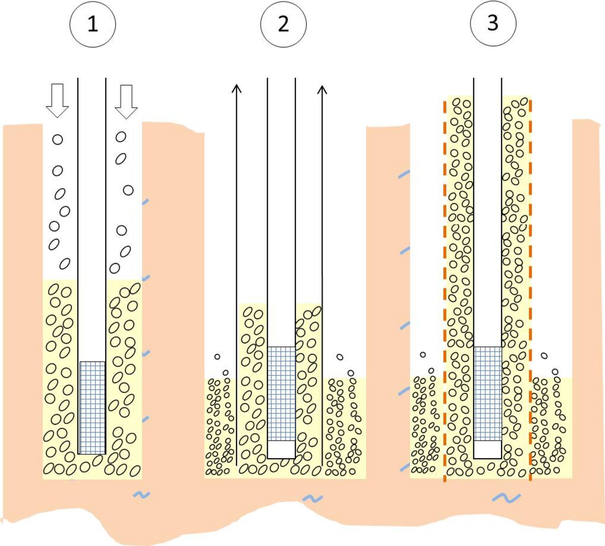
A special care is the responsibility of the well builder if he drills several aquifers during the drilling into the desired groundwater conductor. As a result of the gravity, groundwater from upper layers can penetrate deeper layers (see Figure 8). This process is called hydraulic short circuit.
Groundwater from different layers often has different properties. The water in higher layers can also be caused by direct environmental influences, e.g. agriculture but also damage. In any case, the short circuit must be prevented to ensure the groundwater quality.
In order to prevent the flow of water from different aquifers, barriers must be installed. A common means is the incorporation of poured sealing materials from clay.
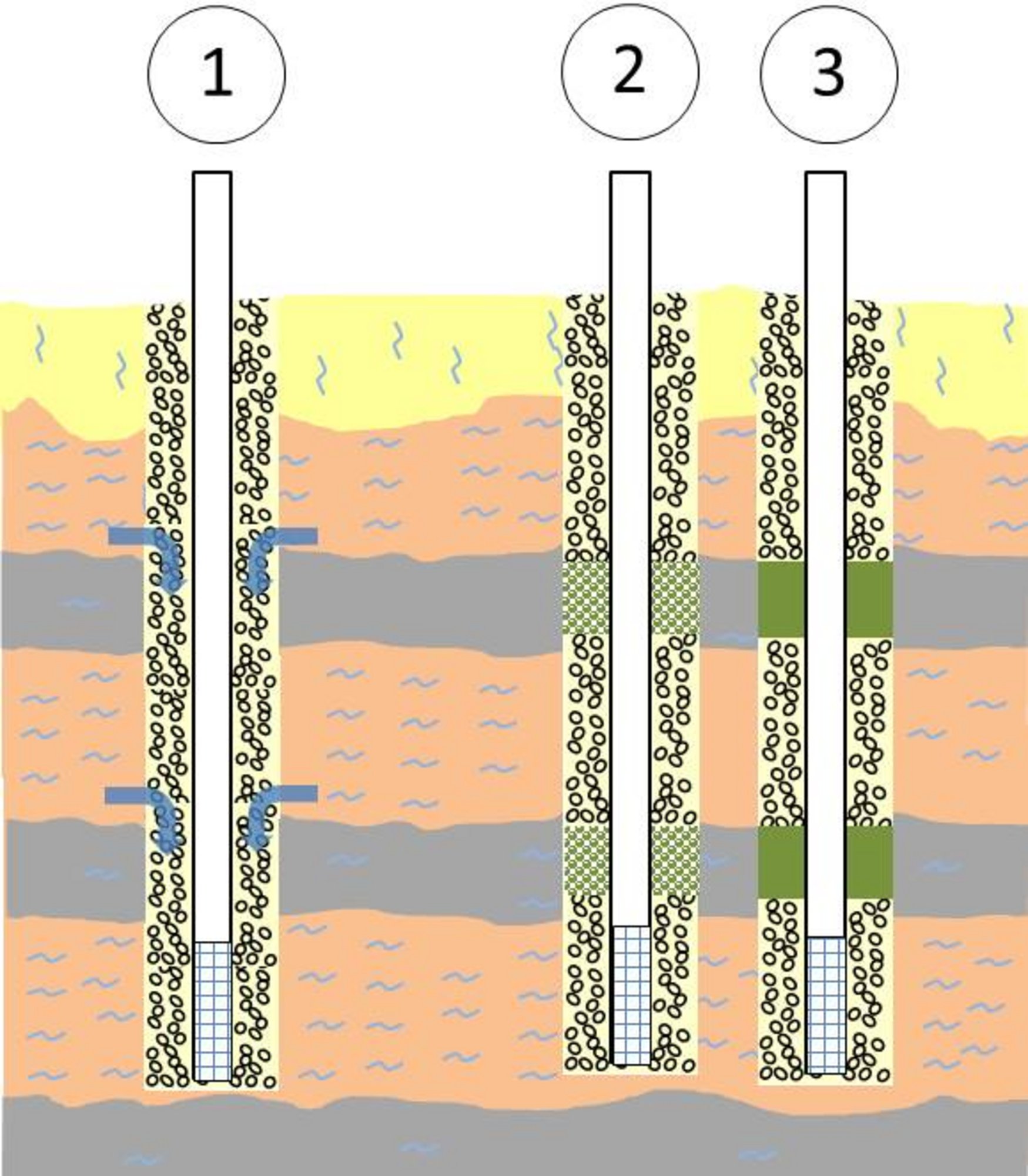
- Representation of a bore through different aquifers without a barrier
- Representation of a bore through different aquifers with freshly poured clay (before swelling).
- Representation of a bore through different aquifers with ready swollen clay
The installation of the locks of clay is similar to the filter gravel. The filter gravel is poured to a short distance below the non-aquifer. In the area of the non-aquifer, clay pellets or clay granules are poured. Subsequently, it is again poured with filter gravel. Covering with filter grains is important, as the clay begins to swell and thereby increases its volume (multiplied). Since expansion is not possible, pressure builds up against the load on the gravel (a so-called "swelling pressure"). Since the clay in swollen state does not allow water to flow , and it also presses into the smallest cavities through the swelling pressure, the clay barrier acts as a precisely adapted seal on the pipe as well as on the mountains. The short circuit between the various groundwater conductors is effectively prevented.
Not every clay granule or clay pellet are equally suitable. The particles have to wait until the source has reached the desired depth. If the particles swell too quickly, they dissipate through the flow as they descend, creating a suspension and no layer. The swelling capability itself determines the magnitude of the swelling pressure and when tightness is achieved. Also important is the so-called local stability as a function of the flow velocity of the groundwater conductor. The swollen clay should remain at the location of the bed and should not be slowly removed or rinsed out. It is important to make the right selection, which fits the conditions of the bore hole.